Packaging line design UK
Packaging line design should begin with the pack journey, not just the machine list. The best layout balances infeed, filling, closing, labelling, coding, inspection, accumulation and operator access.
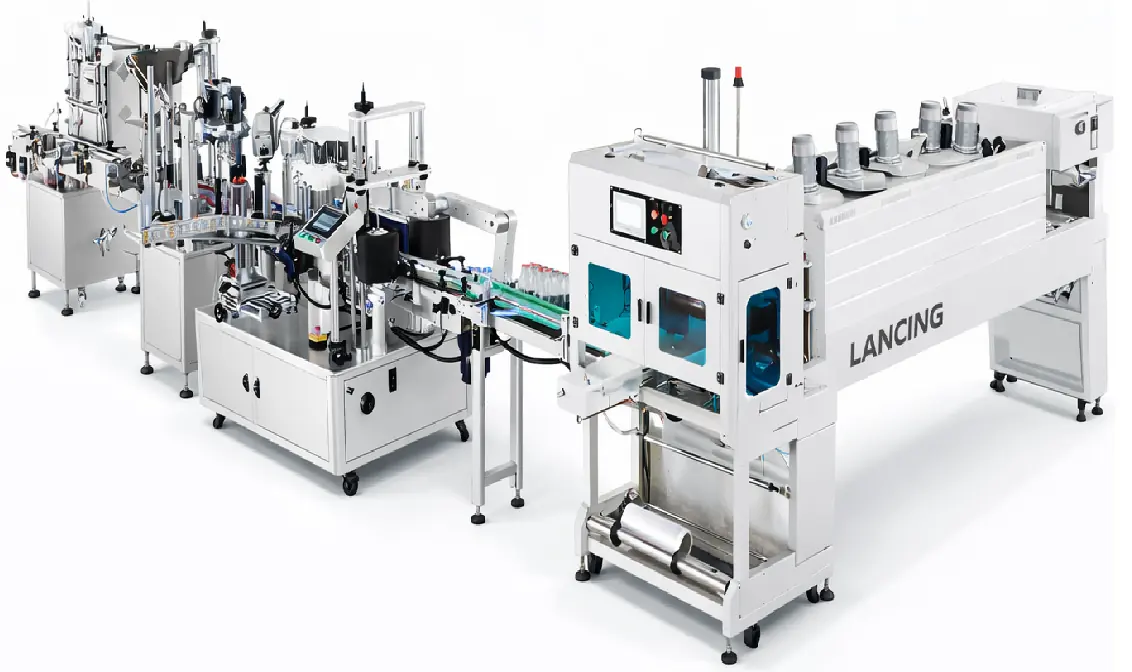
How to specify packaging line design.
Use these points to prepare a stronger machinery enquiry and narrow the equipment range before quotation.
Best-fit applications
Packaging line design UK are most useful when the machine format is matched to the product, pack and operator process rather than chosen from headline speed alone.
- new production cells needing filling, capping and labelling in one flow
- existing lines with bottlenecks between isolated machines
- site layouts where space, access or utilities restrict equipment placement
Details to confirm before selection
Accurate specification starts with samples, real production targets and a clear view of what happens before and after this process.
- available footprint, doors, drainage, extraction and clean-down requirements
- container stability through transfers, curves and accumulation
- reject strategy, coding location and access for maintenance or changeover
Build a practical enquiry
Send product details, filled and empty pack samples, photos or videos of the current process, expected output and any site restrictions. This helps identify whether a standard machine, tooling change or integrated line is the correct route.
- Include product and pack photos where possible.
- State current output, target output and operator involvement.
- Confirm whether the requirement is standalone equipment or line integration.
Packaging line design UK FAQs
Why is line balance important?
A fast filler cannot deliver its rated output if caps, labels, conveyors or collection tables create bottlenecks.
What layout information is needed?
A simple sketch with dimensions, product flow direction, utilities and operator positions is enough to start a technical review.
Can existing machines be included?
Often yes, provided conveyor heights, controls, guarding and product handling can be matched safely.
Continue comparing suitable options.
Use these related pages to narrow the machinery type and prepare a more accurate enquiry.
Complete packaging lines
Integrated filling, capping, labelling and conveyor systems.
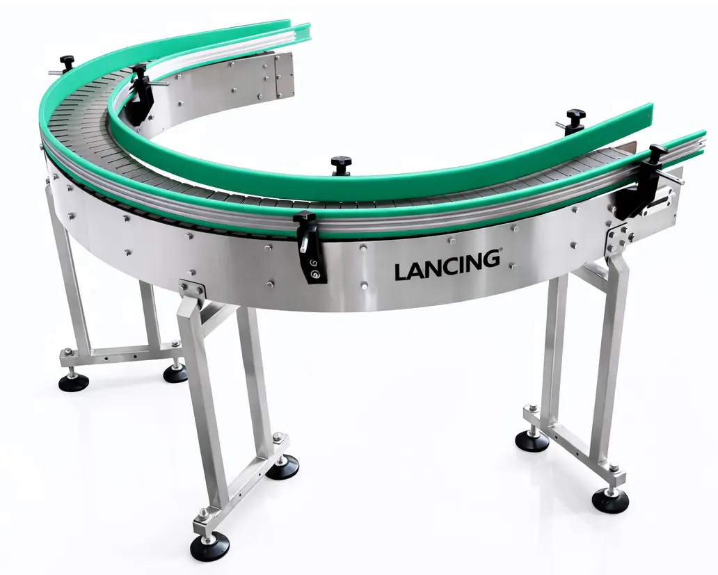
Packaging conveyor systems
Conveyors and accumulation for packaging lines.
Packaging machinery integration UK
Packaging machinery integration for UK production lines, connecting fillers, cappers, labellers, conveyors, coding and end-of-line equipment.
Balance material flow, access and recovery—not only nominal machine speeds.
A practical packaging line layout shows how packs move, where operators work and how the cell responds when one process pauses.
Map the process sequence
Show every value-adding operation, inspection, manual task, accumulation point and reject route from infeed to packed output.
Design access into the footprint
Allow for loading, cleaning, change parts, electrical panels, guarding doors, fault recovery and removal of components for maintenance.
Balance the operating pattern
Use representative cycle behaviour, refill needs, batch changes and expected interruptions rather than multiplying a headline rate by available time.
Layout data to record
| Site datum | Walls, columns, doors, drains, service points, floor changes and restricted areas. |
|---|---|
| Flow direction | Raw material, packaging components, operators, finished goods and waste. |
| Machine envelope | Operating footprint plus doors, panels, change parts and maintenance removal space. |
| Conveyor route | Height, width, curve, transfer and accumulation purpose. |
| Controls and safety | Panel locations, line zones, access requests, emergency-stop boundaries and reset points. |
Acceptance planning
- Name the formats and production materials included in the test.
- Define the required finished-pack checks for each process.
- State permitted operator interventions and refill activity.
- Include controlled stops, restart and fault-recovery observations.
- Record actions, changes and final responsibility for closure.
Packaging line design questions to resolve before layout approval.
A drawing should be treated as a controlled project document whose assumptions are visible and reviewable.
How early should the layout be produced?
Early enough to expose access, utility and interface constraints before machinery configuration is fixed.
What is a line balance?
It is the relationship between process cycle behaviour, pack pitch, buffers, operator tasks and the required finished output.
How should manual work be shown?
Mark loading, inspection, replenishment, changeover, recovery and material movement areas on the layout.
What makes a buffer useful?
It has a defined event to absorb and a controlled way of accepting and releasing packs without damage.
What should be frozen before manufacture?
The approved pack range, critical interfaces, site layout, utility responsibilities, control boundary and acceptance method should be controlled.
Where should detailed FAT and SAT planning sit?
For a complete-line project, use the dedicated Packaging Lines guidance and include the agreed protocol in the project scope.
Prepare a useful machinery enquiry
Send a dimensioned site sketch, current machine list and expected pack flow. The layout can then be reviewed for transfers, access and project boundaries.
Design around good finished output, not isolated machine cycle rates.
The layout should show how product, packaging components, operators and information move through the line. Each buffer and manual task needs a defined purpose.
| Process sequence | List every operation from incoming product and empty pack to the agreed finished output, including coding, inspection, rejection and collection. |
|---|---|
| Cycle behaviour | Record how each operation starts, stops, indexes or runs continuously and how that behaviour changes with different approved formats. |
| Replenishment and material movement | Mark where product, containers, caps, labels, film and secondary packaging are loaded, stored and replenished without obstructing access. |
| Accumulation purpose | Name the interruption or process difference each buffer is intended to absorb and how packs enter, queue and release without damage or loss of orientation. |
| Manual work | Show inspection, loading, unloading, topping-up, changeover, cleaning, recovery and waste-handling positions rather than treating labour as outside the design. |
| Reject and rework route | Identify detection points, safe diversion, containment, reconciliation and the route back into production when rework is permitted. |
| Access and maintenance | Allow for doors, guards, tooling removal, cleaning, routine inspection, control panels, lifting needs and the safe withdrawal of parts. |
| Future formats and retained equipment | Record the known future requirement and verify the condition, controls, working height and capacity of any existing machine included in the layout. |
Freeze the design basis before equipment positions become commitments.
An approved drawing should carry the assumptions needed to interpret it. Dimensions alone do not define transfers, controls, access or operating responsibilities.
Drawing basis
Approved pack range, product flow direction, line datum, working heights, utility points, operator zones and third-party equipment.
Operating basis
Required output pattern, format schedule, replenishment method, changeover approach, starve/block behaviour and permitted manual tasks.
Evidence basis
Design reviews, representative samples, interface checks and the FAT/SAT observations that will demonstrate the installed line against the brief.
Use design gates so layout assumptions remain visible and controlled.
A packaging line drawing should show more than equipment rectangles. It should represent material flow, operating envelopes, access, services, controls zones and the evidence needed before the design is released for manufacture or site work.
Freeze the pack journey
Confirm the sequence, orientation, inspection, rejection, manual work and accumulation purpose before finalising machine positions.
Protect operating access
Allow for loading, cleaning, change parts, guarding doors, panel access, maintenance removal space and operator movement.
Control design changes
Keep approved revisions, assumptions and open actions aligned across supplier drawings, site work, interfaces and acceptance plans.
Information to prepare
- Dimensioned room and installation route.
- Process flow and manual tasks.
- Machine operating and maintenance envelopes.
- Utilities, extraction, drainage and network points.
- Controlled drawing approval and change process.
Continue from this page
Use the most relevant next step to move from initial selection towards a defined, testable project.
Packaging automation project brief
Define requirements that the layout and design must satisfy.
Site-readiness guide
Translate the approved layout into access, services and installation actions.
Controls integration guide
Coordinate conveyor zones, machine states and safety boundaries with the physical design.